Your Emergency light fixture wiring diagram images are available in this site. Emergency light fixture wiring diagram are a topic that is being searched for and liked by netizens today. You can Download the Emergency light fixture wiring diagram files here. Download all free photos.
If you’re searching for emergency light fixture wiring diagram images information related to the emergency light fixture wiring diagram keyword, you have visit the right blog. Our website always gives you suggestions for seeking the maximum quality video and picture content, please kindly surf and find more enlightening video articles and graphics that fit your interests.
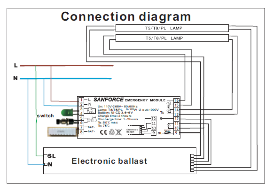
Emergency Light Fixture Wiring Diagram. It shows the components of the circuit as simplified shapes and the talent and signal links surrounded by the devices. Click on the image to enlarge and then save it to your computer by right clicking on the image. Connect building supply wires to the power supply module input wires and feed splices into the junction box. See note 1 under wiring diagram must be connected to either 120 or 277vac of emergency ballast whitered hot 2 this lead must be connected to incoming power either switched or unswitched see wiring diagram - note 2 white common ballast hsg see note 3 under wiring diagram make connection for charge indicat or ballast cover emergency ballast lighting fixture models.
 Non Maintained Emergency Lighting Wiring Diagram Emergency Lighting Led Tubes Diagram From pinterest.com
WIRING DIAGRAM for EMERGENCY OPERATION at 120V-277V with 0-10V DIMMING Emergency Ballast and AC Ballast must be fed from the same circuit LED DIM DRIVER 120V - 277V BODINE BSL17C EMERGENCY LED DRIVER CUSTOMER SHOULD CONNECT ONLY AFTER FINISHING WIRING TO AC POWER. Wiring Diagram Light Fitting New Wiring Diagram For Loop In Lighting. The unit is shipped from the factory with the leads disconnected and capped. Jul 13 2014. To test depress the TEST switch. The diagram below illustrates the typical EM battery backup system.
May be used with other ballasts.
The lighting fixtures are fed from a dedicated emergency-only breaker panel fed directly from the emergency power source which may be a generator or UPS uninterruptable power supply. Depending on the unit you will generally mount the unit or partially mount it before connecting the wiring. Dual head emergency lighting fixture battery 6v 45ah 6v 54w lamps pcb. Collection Marley Baseboard Heater Wiring Diagram Trend Of Electric Light Fixture Wiring Diagram In addition Wiring Diagram provides you with time frame in which the tasks are to be finished. Whether the standard ballast is rapid start or instant start. Wiring diagram with heater.
 Source: ballastshop.com
Route wires along side walls of enclosure to assure proper sign illumination and to protect wires from damage. Dual head emergency lighting fixture battery 6v 45ah 6v 54w lamps pcb. Emergency Light Wiring Diagram wiring diagram is a simplified conventional pictorial representation of an electrical circuit. Emergency Lighting and UL924. The emergency LED lamps will illuminate.
 Source: superbrightleds.com
Collection Marley Baseboard Heater Wiring Diagram Trend Of Electric Light Fixture Wiring Diagram In addition Wiring Diagram provides you with time frame in which the tasks are to be finished. When the source comes online the lights are energized without any switching or transfer equipment. 277v red or orange black white red blue - 120v com battery 6v 45ah 6v 54w lamps pcb. WIRING DIAGRAM for EMERGENCY OPERATION at 120V-277V with 0-10V DIMMING Emergency Ballast and AC Ballast must be fed from the same circuit Easy Installation Product Help Tech Help Line Call our experts 888 RAB-1000 2012 RAB LIGHTING Inc. 277v red or orange black white red blue.
 Source: sanforce-tech.com
To test depress the TEST switch. In terms of connections there are two ways of doing it - you can have the keyswitch just cut the permanent feed leaving all the lights on but the emergency lights in emergency mode or you can have the keyswitch cut all the live feeds so you can easily see which emergency fittings are illuminated. Collection Marley Baseboard Heater Wiring Diagram Trend Of Electric Light Fixture Wiring Diagram In addition Wiring Diagram provides you with time frame in which the tasks are to be finished. Jul 13 2014. EMERGENCY LIGHT MOUNTING PROCEDURE.
 Source: ocantinhodavih.blogspot.com
Emergency Lighting and UL924. The one disadvantage to this arrangement is that the emergency fixtures will be dark when. When the switch is released the lamps will go off. See note 1 under wiring diagram must be connected to either 120 or 277vac of emergency ballast whitered hot 2 this lead must be connected to incoming power either switched or unswitched see wiring diagram - note 2 white common ballast hsg see note 3 under wiring diagram make connection for charge indicat or ballast cover emergency ballast lighting fixture models. The unit is shipped from the factory with the leads disconnected and capped.
 Source: cjanderson.com
EMERGENCY LIGHT MOUNTING PROCEDURE. The lighting fixtures are fed from a dedicated emergency-only breaker panel fed directly from the emergency power source which may be a generator or UPS uninterruptable power supply. 277v red or orange black white red blue. To test depress the TEST switch. How many lamps the emergency ballast will light up if power fails usually one or two.
 Source: wiringdiagramall.blogspot.com
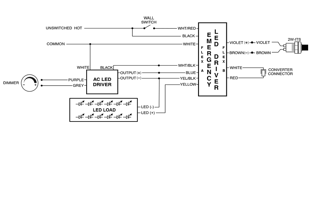
If your wall is not already wired for the fixture your will need to consult an electrician to run the necessary wiring. Wiring Diagram Light Fitting New Wiring Diagram For Loop In Lighting. EMERGENCY LIGHT MOUNTING PROCEDURE. The detailed wiring diagram below illustrates that the emergency LED driver powers the LED LOAD using the AC LED driver input in normal power mode and with battery power in emergency mode. E m e r g e n c y b a l l a s t wall switch whtred red white violet.
 Source: alibaba.com
To test depress the TEST switch. When the switch is released the lamps will go off. The detailed wiring diagram below illustrates that the emergency LED driver powers the LED LOAD using the AC LED driver input in normal power mode and with battery power in emergency mode. 277v red or orange black white red blue. WIRING DIAGRAM for EMERGENCY OPERATION at 120V-277V with 0-10V DIMMING Emergency Ballast and AC Ballast must be fed from the same circuit Easy Installation Product Help Tech Help Line Call our experts 888 RAB-1000 2012 RAB LIGHTING Inc.
 Source: youtube.com
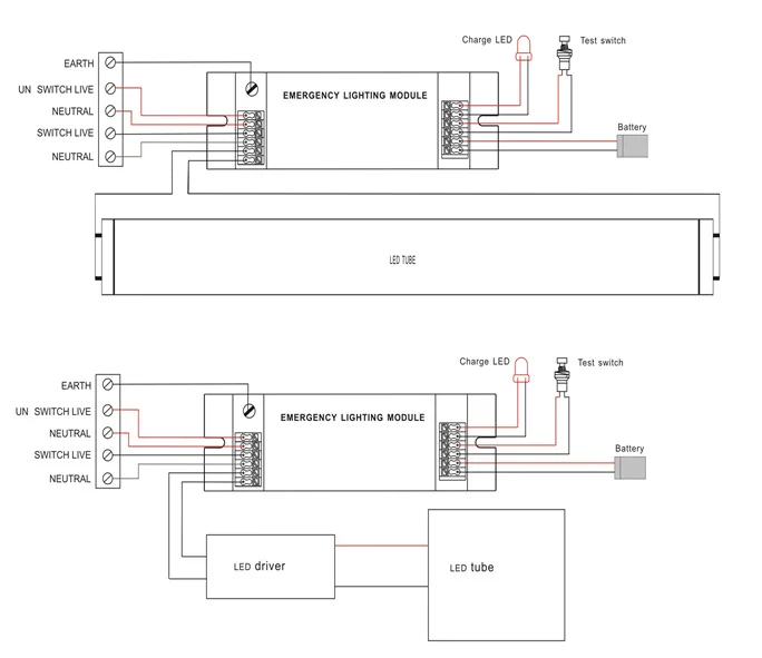
Consult the factory for other wiring diagrams. The diagram below illustrates the typical EM battery backup system. Youll be capable to learn exactly once the assignments needs to be completed which makes it easier to suit your needs to effectively handle your time and effort. WIRING DIAGRAM for EMERGENCY OPERATION at 120V-277V with 0-10V DIMMING Emergency Ballast and AC Ballast must be fed from the same circuit LED DIM DRIVER 120V - 277V BODINE BSL17C EMERGENCY LED DRIVER CUSTOMER SHOULD CONNECT ONLY AFTER FINISHING WIRING TO AC POWER. E m e r g e n c y b a l l a s t wall switch whtred red white violet.
 Source: wiringdiagramall.blogspot.com
The detailed wiring diagram below illustrates that the emergency LED driver powers the LED LOAD using the AC LED driver input in normal power mode and with battery power in emergency mode. WIRING DIAGRAM for EMERGENCY OPERATION at 120V-277V with 0-10V DIMMING Emergency Ballast and AC Ballast must be fed from the same circuit Easy Installation Product Help Tech Help Line Call our experts 888 RAB-1000 2012 RAB LIGHTING Inc. Wiring Diagram Light Fitting Print Wiring Diagram For Fluorescent. For 120V supply connect the line wire to the black lead and-for 277V supply connect the line wire to the orange lead. BATTERY COULD HAVE CHARGE SHOCK.

EMERGENCY LIGHT MOUNTING PROCEDURE. If your wall is not already wired for the fixture your will need to consult an electrician to run the necessary wiring. Route wires along side walls of enclosure to assure proper sign illumination and to protect wires from damage. See note 1 under wiring diagram must be connected to either 120 or 277vac of emergency ballast whitered hot 2 this lead must be connected to incoming power either switched or unswitched see wiring diagram - note 2 white common ballast hsg see note 3 under wiring diagram make connection for charge indicat or ballast cover emergency ballast lighting fixture models. The wiring uses 120 or 277v AC electrical power.
 Source: pinterest.com
The diagram below illustrates the typical EM battery backup system. WIRING DIAGRAM for EMERGENCY OPERATION at 120V-277V with 0-10V DIMMING Emergency Ballast and AC Ballast must be fed from the same circuit Easy Installation Product Help Tech Help Line Call our experts 888 RAB-1000 2012 RAB LIGHTING Inc. Route wires along side walls of enclosure to assure proper sign illumination and to protect wires from damage. EMERGENCY OPERATION VIOLET LEADS WIRING DIAGRAMS 1 2 2 T8-T12 Single Bipin 4 T5 28W T8-T12 Single Bipin One Lamp One Lamp Connected Disconnected 1 2 3 4 5 6 7 8 1 2 3 4 5 6 7 8 The 6 violet leads provide the lamp selection option. When the switch is released the lamps will go off.
 Source: upshine.com
Standard fluorescent ballasts have one wiring diagram. Route wires along side walls of enclosure to assure proper sign illumination and to protect wires from damage. E m e r g e n c y b a l l a s t wall switch whtred red white violet. To test depress the TEST switch. Wiring Diagram Light Fitting Print Wiring Diagram For Fluorescent.
Source: ocantinhodavih.blogspot.com
EMERGENCY LIGHT MOUNTING PROCEDURE. To test depress the TEST switch. Collection Marley Baseboard Heater Wiring Diagram Trend Of Electric Light Fixture Wiring Diagram In addition Wiring Diagram provides you with time frame in which the tasks are to be finished. THE EMERGENCY BALLAST WIRING GUIDE This Document has been customized to contain a wide library of individual dia-grams for various installation applications. Youll be capable to learn exactly once the assignments needs to be completed which makes it easier to suit your needs to effectively handle your time and effort.
 Source: wiringdiagramall.blogspot.com
Depending on the unit you will generally mount the unit or partially mount it before connecting the wiring. The wiring uses 120 or 277v AC electrical power. WIRING DIAGRAM for EMERGENCY OPERATION at 120V-277V with 0-10V DIMMING Emergency Ballast and AC Ballast must be fed from the same circuit Easy Installation Product Help Tech Help Line Call our experts 888 RAB-1000 2012 RAB LIGHTING Inc. Fluorescent light with battery backup wiring diagram Emergency Fluorescent Light Circuit Diagram Inspirational Emergency Fluorescent Light Circuit Diagram Best How to Wire A. For 120V supply connect the line wire to the black lead and-for 277V supply connect the line wire to the orange lead.
 Source: pinterest.com
Wiring Diagram Light Fitting Print Wiring Diagram For Fluorescent. Collection Marley Baseboard Heater Wiring Diagram Trend Of Electric Light Fixture Wiring Diagram In addition Wiring Diagram provides you with time frame in which the tasks are to be finished. To test depress the TEST switch. If your wall is not already wired for the fixture your will need to consult an electrician to run the necessary wiring. EMERGENCY LIGHT MOUNTING PROCEDURE.
 Source: youtube.com
277v red or orange black white red blue - 120v com battery 6v 45ah 6v 54w lamps pcb. The detailed wiring diagram below illustrates that the emergency LED driver powers the LED LOAD using the AC LED driver input in normal power mode and with battery power in emergency mode. Route wires along side walls of enclosure to assure proper sign illumination and to protect wires from damage. The unit is shipped from the factory with the leads disconnected and capped. Wiring Diagram Light Fitting New Wiring Diagram For Loop In Lighting.
 Source: pinterest.com
WIRING DIAGRAM REMOTE CAPABLE REGULAR 1. The unit is shipped from the factory with the leads disconnected and capped. WIRING DIAGRAM REMOTE CAPABLE REGULAR 1. THE EMERGENCY BALLAST WIRING GUIDE This Document has been customized to contain a wide library of individual dia-grams for various installation applications. EMERGENCY OPERATION VIOLET LEADS WIRING DIAGRAMS 1 2 2 T8-T12 Single Bipin 4 T5 28W T8-T12 Single Bipin One Lamp One Lamp Connected Disconnected 1 2 3 4 5 6 7 8 1 2 3 4 5 6 7 8 The 6 violet leads provide the lamp selection option.
 Source: dmflighting.com
To test depress the TEST switch. WIRING DIAGRAM for EMERGENCY OPERATION at 120V-277V with 0-10V DIMMING Emergency Ballast and AC Ballast must be fed from the same circuit LED DIM DRIVER 120V - 277V BODINE BSL17C EMERGENCY LED DRIVER CUSTOMER SHOULD CONNECT ONLY AFTER FINISHING WIRING TO AC POWER. Collection Marley Baseboard Heater Wiring Diagram Trend Of Electric Light Fixture Wiring Diagram In addition Wiring Diagram provides you with time frame in which the tasks are to be finished. For 120V supply connect the line wire to the black lead and-for 277V supply connect the line wire to the orange lead. 277v red or orange black white red blue - 120v com battery 6v 45ah 6v 54w lamps pcb.
This site is an open community for users to do sharing their favorite wallpapers on the internet, all images or pictures in this website are for personal wallpaper use only, it is stricly prohibited to use this wallpaper for commercial purposes, if you are the author and find this image is shared without your permission, please kindly raise a DMCA report to Us.
If you find this site serviceableness, please support us by sharing this posts to your own social media accounts like Facebook, Instagram and so on or you can also save this blog page with the title emergency light fixture wiring diagram by using Ctrl + D for devices a laptop with a Windows operating system or Command + D for laptops with an Apple operating system. If you use a smartphone, you can also use the drawer menu of the browser you are using. Whether it’s a Windows, Mac, iOS or Android operating system, you will still be able to bookmark this website.


