Your Exhaust fan interlock wiring diagram images are available in this site. Exhaust fan interlock wiring diagram are a topic that is being searched for and liked by netizens today. You can Find and Download the Exhaust fan interlock wiring diagram files here. Download all free photos and vectors.
If you’re looking for exhaust fan interlock wiring diagram pictures information linked to the exhaust fan interlock wiring diagram topic, you have pay a visit to the ideal site. Our site frequently provides you with suggestions for refferencing the maximum quality video and picture content, please kindly surf and find more enlightening video articles and graphics that fit your interests.
Exhaust Fan Interlock Wiring Diagram. If I turn on the ventilation fan the furnace fan AND the bathroom fan come on. A common problem when combining a building automation system with a 3-phase fan that must open a damper before operating is the damper end switch interlock for the motor starter HAND position. Locate the exhaust duct on top of the hood. If the ansul system should discharge.
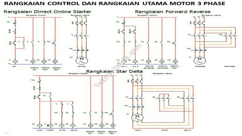
 Wiring Kontrol Dan Motor 3 Phase Teknisi Listrik From teknik-listrik.com
A common problem when combining a building automation system with a 3-phase fan that must open a damper before operating is the damper end switch interlock for the motor starter HAND position. Electrical wiring and connections should be done in accordance with local ordinances and the National. These systems are designed to control activate and operate the exhaust fans supply fans CORE systems and wash system dependent on the HMI settings and temperature sensors. Working of Electrical Interlocking. Exhaust fan wire diagram. As-built wiring diagrams are furnished with each control by the factory and are attached either to the door of the unit or provided within a paperwork pouch internal to the panel.
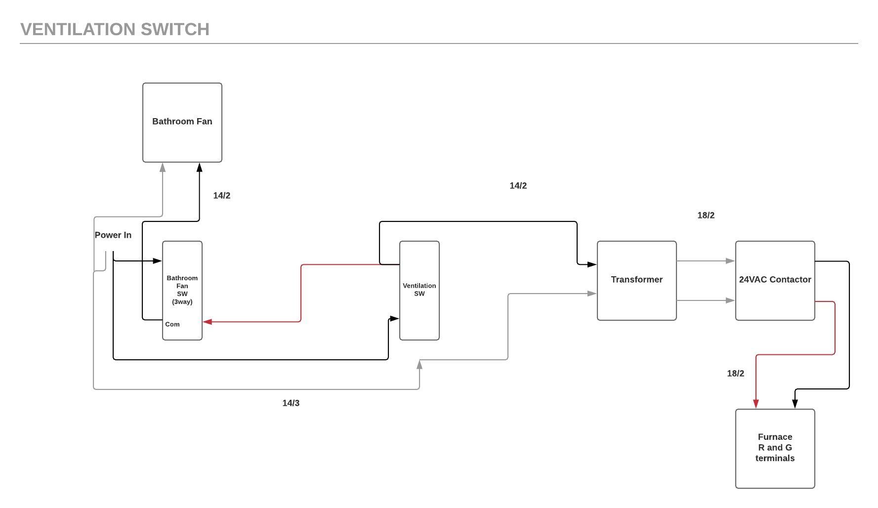
Im thinking i would need a 3 way switch at the bathroom fan.
And exhaust fans continuous operation in fire lights off in fire optional. Working of Electrical Interlocking. I tried searching but didnt find much. Im thinking i would need a 3 way switch at the bathroom fan. Exhaust Fan Interlock Wiring Diagram The electrical wiring would be connected with the power source in and load out to the bathroom exhaust fan a neutral wire if required and a ground wire. Ad Improve Your Business ROI - Get A Better Deal On Exhaust Fans.
 Source: pinterest.com
Download Bathroom Exhaust Fan Wiring Diagram For Switch To Light PDF Subject. If the ansul system should discharge. What i did was run 143 from fan switch box to a central switch then a 142 to a relay box to run the furnace. That black wire will go on a NC contact on the relay. Refer to the motor manufacturers data on the motor for wiring diagrams on.
 Source: wiringdiagramall.blogspot.com
Does anyone have a wiring diagram. Control Circuit Diagrams Control Circuit Diagram Standard Control This is an example of a generic wiring diagram for standard control. Download Bathroom Exhaust Fan Wiring Diagram For Switch To Light PDF Subject. I also had a fan heater light. Exhaust fan wire diagram.
 Source: wiringdiagramall.blogspot.com
Understand this entire document. Refer to the motor manufacturers data on the motor for wiring diagrams on. Find a spot to mount the sensor where it will not interfere. That black wire will go on a NC contact on the relay. As Contactor M1 energies its all normally Close NC links open and the other normally open NO links used in the circuit close.
 Source: in.pinterest.com
If the ansul system should discharge. Turning on any piece of cooking equipment under a hood will turn on the exhaust fan for that hood. To test the systems fire suppression interlock and auto fan control for IMC 507211 compliance follow the test procedures in the next section. There should be an 183 from the relay to the furnace. Contactor interlock wiring diagram.
 Source: pinterest.com
As-built wiring diagrams are furnished with each control by the factory and are attached either to the door of the unit or provided within a paperwork pouch internal to the panel. Working of Electrical Interlocking. All starters provided by others external to. This diagram has 12 sensors which provide temperature interlock function for two exhaust fans and one supply fan. Im thinking i would need a 3 way switch at the bathroom fan.
 Source: wiringdiagramall.blogspot.com
Electrical wiring and connections should be done in accordance with local ordinances and the National. If I turn on the ventilation fan the furnace fan AND the bathroom fan come on. Wiring must be in accordance with ASNZS30002007 and local supply regulations. Refer to the motor manufacturers data on the motor for wiring diagrams on. 39 complete schematic diagram for small packaged unit westinghouse electric corp 8 pictorial diagrams.
 Source: wiringdiagramall.blogspot.com
Fan Control Centers Accurex. Control Circuit Diagrams Control Circuit Diagram Standard Control This is an example of a generic wiring diagram for standard control. Find a spot to mount the sensor where it will not interfere. It shows the components of the circuit as simplified shapes as well as the power as well as signal connections in between the gadgets. See wiring diagram and installation instructions page3 for wiring requirements.
 Source: wiringdiagramall.blogspot.com
As-built wiring diagrams are furnished with each control by the factory and are attached either to the door of the unit or provided within a paperwork pouch internal to the panel. Refer to the motor manufacturers data on the motor for wiring diagrams on. If I turn on the ventilation fan the furnace fan AND the bathroom fan come on. I tried searching but didnt find much. I will clarify what the furnace fan interlock is and what it does.
 Source: id.pinterest.com
Exhaust Fan Interlock Wiring Diagram The electrical wiring would be connected with the power source in and load out to the bathroom exhaust fan a neutral wire if required and a ground wire. 39 complete schematic diagram for small packaged unit westinghouse electric corp 8 pictorial diagrams. This diagram has 12 sensors which provide temperature interlock function for two exhaust fans and one supply fan. When we push the ON-1 button to energies the M1 Contactor or starts M1 Motor then circuit complete through Fuse Overload relays trip link OFF Push -1 and ON Push 1. Each fan zone has several parameters that communicate with the system on how to operate.
 Source: teknik-listrik.com
And exhaust fans continuous operation in fire lights off in fire optional. And motor M1 Starts to run. Turning on any piece of cooking equipment under a hood will turn on the exhaust fan for that hood. If the ansul system should discharge. These systems are designed to control activate and operate the exhaust fans supply fans CORE systems and wash system dependent on the HMI settings and temperature sensors.
 Source: hvacquick.com
Each fan zone has several parameters that communicate with the system on how to operate. For Bathroom Exhaust Fan Wiring Diagram For Switch To Light PDF More Information you can get it easily in this portal. Control Circuit Diagrams Control Circuit Diagram Standard Control This is an example of a generic wiring diagram for standard control. Wiring must be in accordance with ASNZS30002007 and local supply regulations. Interlock wiring diagram for exhaust fan and cooking equipment.
 Source: pinterest.com
Feb 11 2020 wiring diagram for a bathroom exhaust fan switch. Electrical wiring and connections should be done in accordance with local ordinances and the National. Im thinking i would need a 3 way switch at the bathroom fan. What i did was run 143 from fan switch box to a central switch then a 142 to a relay box to run the furnace. And exhaust fans continuous operation in fire lights off in fire optional.
 Source: wiringdiagramall.blogspot.com
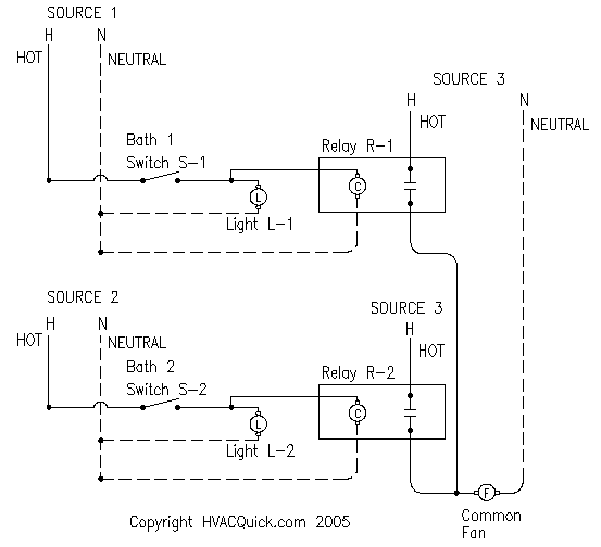
You should have a relay with a 120 volt coil between the switch and the exhaust fan. This is easy to do when the fan starter is in the AUTO position the control system can power the damper actuator and a damper end switch will close the. Locate the exhaust duct on top of the hood. Does anyone have a wiring diagram. These systems are designed to control activate and operate the exhaust fans supply fans CORE systems and wash system dependent on the HMI settings and temperature sensors.
 Source: pinterest.com
PROTECTION Fuses in the circuit should be regarded as protecting the wiring only against short circuit they are not suitable for overload protection. All starters provided by others external to. Locate the exhaust duct on top of the hood. A common problem when combining a building automation system with a 3-phase fan that must open a damper before operating is the damper end switch interlock for the motor starter HAND position. PROTECTION Fuses in the circuit should be regarded as protecting the wiring only against short circuit they are not suitable for overload protection.
 Source: manualzz.com
As Contactor M1 energies its all normally Close NC links open and the other normally open NO links used in the circuit close. I have traced the wires and included a wiring diagram of the existing circuit. Grab Bathroom Exhaust Fan Wiring Diagram For Switch To Light PDF Kindle on PDF Bank with Free. Fan Control Centers Accurex. Electrical wiring and connections should be done in accordance with local ordinances and the National.
 Source: shdelectric.ca
I tried searching but didnt find much. Exhaust Fan Interlock Wiring Diagram The electrical wiring would be connected with the power source in and load out to the bathroom exhaust fan a neutral wire if required and a ground wire. Feb 11 2020 wiring diagram for a bathroom exhaust fan switch. If I turn on the ventilation fan the furnace fan AND the bathroom fan come on. Each fan zone has several parameters that communicate with the system on how to operate.
 Source: wiringdiagramall.blogspot.com
Wiring must be in accordance with ASNZS30002007 and local supply regulations. Electrical wiring and connections should be done in accordance with local ordinances and the National. As-built wiring diagrams are furnished with each control by the factory and are attached either to the door of the unit or provided within a paperwork pouch internal to the panel. Wiring must be in accordance with ASNZS30002007 and local supply regulations. As Contactor M1 energies its all normally Close NC links open and the other normally open NO links used in the circuit close.
 Source: pinterest.com
Turning off the last pice of cooking equipment under a hood will turn off the exhaust fan for that hood. I have traced the wires and included a wiring diagram of the existing circuit. In alberta you have to interlock the primary exhaust with the furnace. Wiring diagrams are shown on pages N-69. And exhaust fans continuous operation in fire lights off in fire optional.
This site is an open community for users to do submittion their favorite wallpapers on the internet, all images or pictures in this website are for personal wallpaper use only, it is stricly prohibited to use this wallpaper for commercial purposes, if you are the author and find this image is shared without your permission, please kindly raise a DMCA report to Us.
If you find this site good, please support us by sharing this posts to your own social media accounts like Facebook, Instagram and so on or you can also save this blog page with the title exhaust fan interlock wiring diagram by using Ctrl + D for devices a laptop with a Windows operating system or Command + D for laptops with an Apple operating system. If you use a smartphone, you can also use the drawer menu of the browser you are using. Whether it’s a Windows, Mac, iOS or Android operating system, you will still be able to bookmark this website.


